Step 1 – Fasten Board Mounting Studs
Using four 5/8" [16mm] black screws and nuts, fasten the ITX motherboard mounting studs, as shown. (NOTE that good side/bad side of material doesn’t matter with this part, and the mounting holes are duplicated/mirrored so it can be flipped either way).
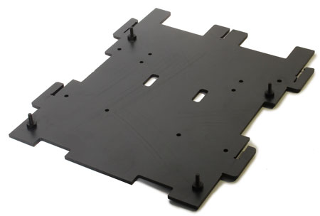
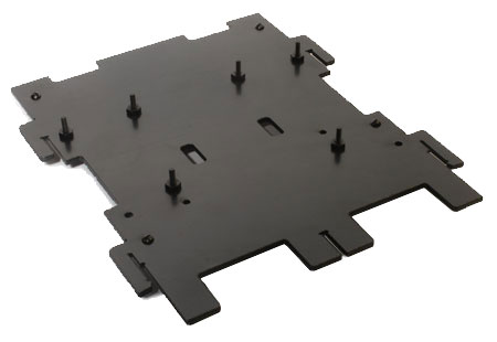
Similarly, install six 5/8" [16mm] PCB mounting studs on the other side, as shown:
Step 2 – Assemble 6 Parts
Snap together 6 chassis parts as show, paying attention to good-side-out for applicable parts. Make sure the motherboard mounting studs are pointing up.
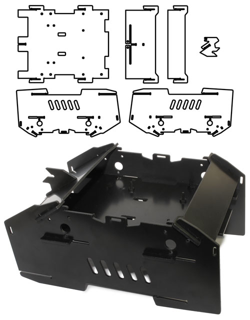
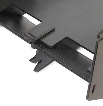
Check that the dock V-interface part is slotted into the motherboard mounting plate, as well as the lower rear panel, as shown:
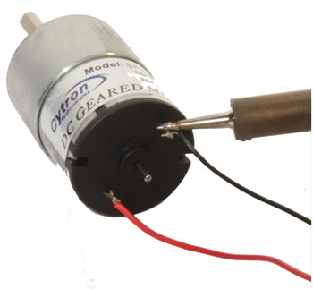
Step 3 – Solder Leads to Motors
Strip the ends (approx 1/4" [6mm]) of 2 of each of 10" [250mm] red and black wires, and one of each of 5" [125mm] red and black wires. Solder them to the motor terminals; red to positive, black to negative. Look for the small ‘+’ molded into the housing, indicating the positive terminal.
2 motors will get the longer leads, the other will have shorter leads (the other, with the encoder, is pre-wired).
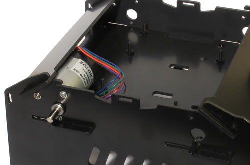
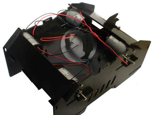
Step 4 – Install Motors
Install 4 motors using M3 x 5mm screws with phillips drive and washers, 3 per motor, being careful not to over-tighten as the threads can strip. (CAUTION don’t try to use the charge terminal screws, which look similar but have a slightly larger thread and slotted drive). Washers should go between the screw-head and the outside of the frame. The motor with the encoder should go at the robot’s right forward position, as shown below:
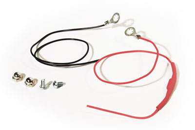
Step 5 – Install Charge Leads
Find the red and black 12" [300mm] length solid core wire leads with ring terminals on them, as well as a two acorn nuts, and two #6 machine screws with slotted drive (CAUTION: these look a lot like the motor mounting screws mentioned above, but they aren’t the same thread):
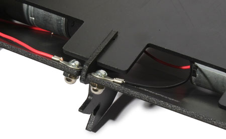
Fasten them to the two holes in the lower rear panel, with the positive (red) lead on ROBOT’S LEFT. IT IS VERY IMPORTANT TO GET THE POLARITY RIGHT!
Step 6 – Install Battery Velcro Strap
Loop the velcro strap for the battery through the rectangular holes, as shown:
Step 7 – Install Motherboard
Fasten the motherboard to the top studs with #6 black plastic nuts, with the ports facing towards the rear.
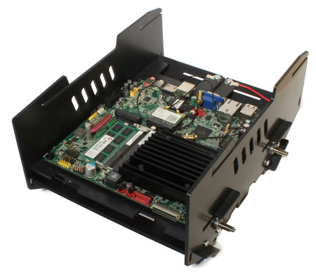
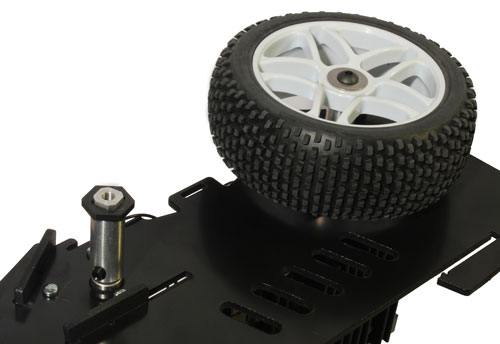
Step 8 – Install Wheels
Each wheel consists of the following parts: wheel, black steel M5 hub screw, black steel M5 set screw, large washer, aluminum wheel hub adapter, and black ABS plastic hex adapater:
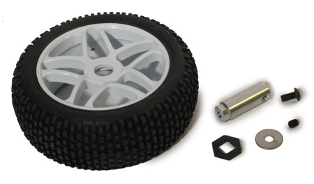
Fasten the aluminum part to the motor shaft with the set screw against the flat of the shaft (using single set screw per wheel is fine). Then push the plastic hex adapter over the top of the aluminum part, and install the wheel using the screw and washer.
NEXT: Chassis Wiring