Step 1 – Power PCB Install
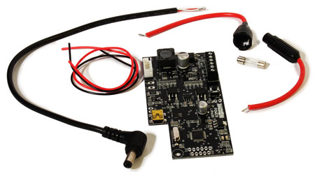
Get the Xaxxon Power LiPo3S PCB, 5A fuse, fuse holder, motherboard power lead (5.5 × 2.5 barrel connector shown, your setup may vary), and 10" [250mm] board connecting red and black wires.
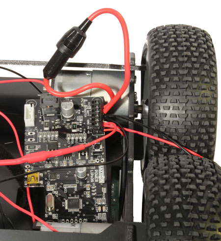
Position the Power PCB on the underside of the chassis, robot’s left side, with the USB port facing rearwards. Locate the “charge leads” with ring terminals you fastened in the previous assembly step. Hook up all wiring to the Power PCB screw terminal, stripping the ends of the wires to approx. 1/4" [6mm] as necessary. Match the wires with the notations on the board as follows:
- Motherboard POSITIVE wire to either one of the two “+V” terminals
- Motherboard GROUND to either one of the two “-GND” terminals
- Combine the RED charge POSITIVE lead and the RED board connecting POSITIVE lead together into the remaining “+V” terminal
- Combine the BLACK charge NEGATIVE lead and the BLACK board connecting NEGATIVE lead together into the remaining “-GND” terminal
- Assemble the fuse in it’s holder and wire the two ends into the two “BATT SWITCH” terminals
(TIP: it helps to pre-bend the heavy gauge fuse wires so it attaches in a decent position, BUT be careful because it’s easy to mangle the internal fuse contacts while doing this – check the continuity after with a multimeter and pull apart and straighten if necessary)
If your motherboard doesn’t have on-board wide-input power, and you’re using the Xaxxon ATX power kit (instead of the barrel connector motherboard power lead as shown above):
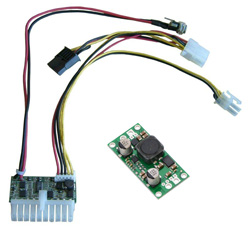
Modify the above line item wiring instructions as follows:
- Red POSITIVE input/Vin wire coming from the regulator, to either one of the two “+V” terminals
- Black GROUND wire coming from the regulator, to either one of the two “-GND” terminals
NOTE: The ATX Power Kit’s regulator PCB needs to be electrically shielded from any other bare metal/conductive elements in the underside of the robot, so affix a piece of plastic to the bottom of the board (or some similar solution).
When wiring is complete, give each wire a tug after tightening the terminals, to make sure they’re firmly connected.
Connect a USB cable, and fasten the board to the studs using #6 black plastic nuts:
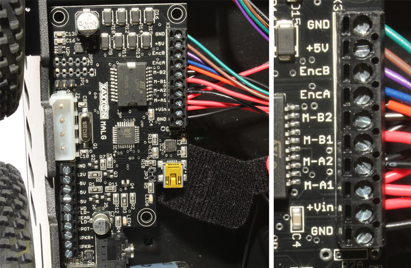
Step 2 – MALG PCB Motor Wiring
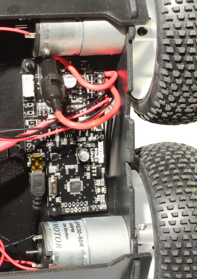
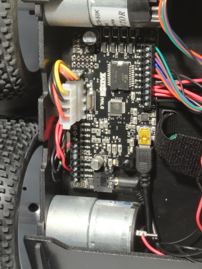
Orient the Xaxxon MALG PCB on robot’s right, underside, with the USB port facing rearwards. Strip the motor leads to approx 1/4" [6mm] – you might have to strip the motor-with-encoder leads a bit more than they are. (Note that this motor is actually wired to turn reverse from the other motors… this is reflected in the directions below).
Going from top-down in the photo:
- GREEN motor-with-encoder wire to “GND” terminal (the upper one, as shown in photo below)
- BROWN motor-with-encoder wire to “+5V” terminal
- PURPLE motor-with-encoder wire to “EncB” terminal
- BLUE motor-with-encoder wire to “EncA” terminal
- RED motor-with-encoder wire, combined with BLACK robot’s right/rear motor wire to “M-B2” terminal
- BLACK motor-with-encoder wire, combined with RED robot’s right/rear motor wire to “M-B1” terminal
- BLACK robot’s left/front wire, combined with BLACK robot’s left/rear motor wire to “M-A2” terminal
- RED robot’s left/front wire, combined with RED robot’s left/rear motor wire to “M-A1” terminal
- RED wire board connecting lead coming from Power PCB “+V” terminal to “+Vin” terminal
- BLACK wire board connecting lead coming from Power PCB “-GND” terminal to “GND” terminal
Give each wire a tug after tightening the terminals, to make sure they’re firmly connected. Note that the red and black motor-with-encoder wires are very thin gauge, so they might need even more insulation removed and the wire folded over, to avoid slipping out when combined with the larger wires.
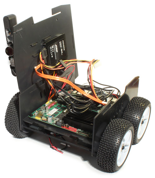
Step 3 – Hook Up SSD, Route Upper Cables Through
We find it’s easiest to do this step with the chassis upright on its wheels, and the upper assembly held vertically by lodging the top plate between the chassis and the wheels on robot’s right.
If an SSD is connected to the top plate, connect power and data to the motherboard and run a 4-pin Molex extension from the Sata power, thru to underneath via the side gap in the motherboard base panel (you’ll likely have to flex the chassis side panel outwards to get the male Molex connector through). Run all the other wires from the upper assembly through to the bottom, and fold/tie up the camera (and Xtion if it’s installed) cable(s).
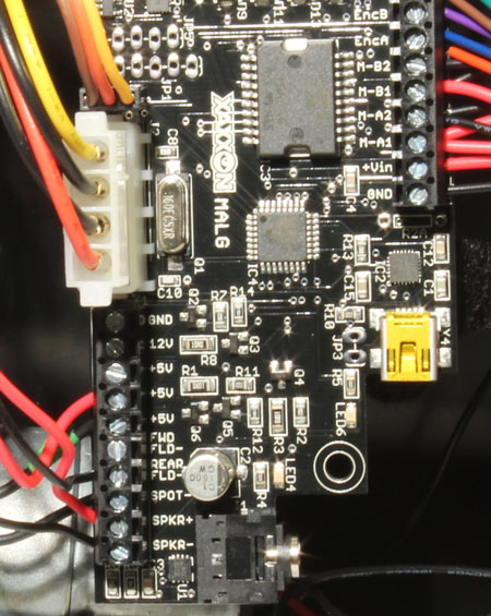
Step 4 – Finish MALG PCB Hookup
Turn the setup on end, so you can wire the rest of the MALG inputs:
Strip 1/4" [6mm] insulation off wire ends as necessary.
Going from top down, left side of the photo below, connect as follows:
- Connect 3-wire servo with lightest-colored wire (signal) towards the inside of the board
- Plug in the Molex extension
- leave “GND” terminal empty
- leave “12V” terminal empty
- leave topmost “+5V” terminal empty
- Dock LED RED wire to the middle “+5V” terminal
- Spot LED POSITIVE wire to lowest “+5V” terminal
- leave “FWD FLD-” terminal empty
- Dock LED BLACK wire to “REAR FLD-” terminal
- Spot LED NEGATIVE wire to “SPOT-” terminal
- Speaker RED wire to “SPKR+”
- Speaker BLACK wire to “SPKR-”
As usual, check each wire with a tug after tightening the terminals.
Install the 3.5mm audio connector and USB cable, and fasten the MALG onto the 3 studs using #6 black plastic nuts:
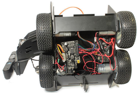
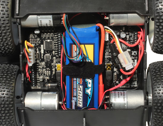
Step 5 – Install Battery
Install but DON’T PLUG THE BATTERY IN YET!
Snap the clear plastic balance plug saver onto the battery JST connector, organize all of the wires out of the way, and strap the battery in place. The Battery should be oriented so the leads are robot’s front left, with the main (unused) heavy gauge leads trapped by the strap, out of the way. DO NOT run any wires under the battery.
WARNING
With the battery installed, make sure the main, unused heavy gauge live power lead coming from the battery is NOT dangerously close to any untrimmed wires soldered to the robot’s-left-rear motor contact, like this:
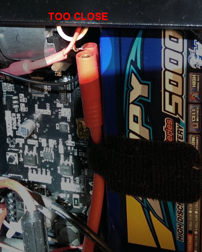
Ensure the motor lead is trimmed clean, and well clear of the battery lead, otherwise any contact could cause permanent damage to the MALG PCB.
NEXT: Wiring Test