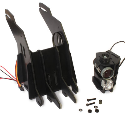
Step 1- Find Pivot Hardware
To attach the camera and light assembly, you’ll need the two 3/4" [20mm] black plastic screws, 2 washers, 2 nuts, and the 1/4" [6mm] spacer. You’ll also need a flat screwdriver, and some needlenose pliers.
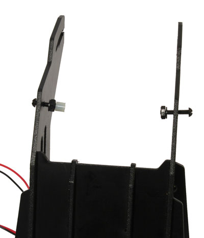
Step 2 – Loosely Install Pivot Hardware
With the screws though the pivot holes, install a washer and nut on each. For robot’s left (right in the photo below), just barely screw the nut on. For robot’s right (left in the photo), screw the nut on just enough to be able to slide the spacer on next to it:
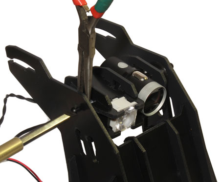
Step 3 – Position Camera and Light and Belt, Tighten Robot’s Right Pivot
Make sure the belt tension screw is fully-backed off, toward robot’s rear (you won’t be tightening it until you calibrate the tilt servo later, after the software is setup). Loop the belt around the pulley of the camera and light assembly, while that assembly is still outside the frame. Then slide it into position, lining up the pivot holes. Tighten the robot’s right pivot firmly, make sure the screw goes into the hole in the frame near the spotlight:
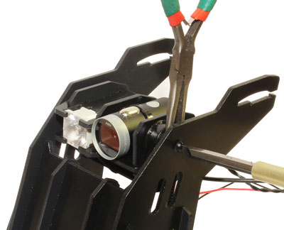
Step 4 – Tighten Robot’s Left Pivot
Tighten the left pivot. If belt seems too tight, make sure it’s not hung up anywhere below.
Step 5(A) – Mount Xtion Sensor
(If applicable) Position the xtion sensor, and slide the bracket in to hold it in place. Note how the cable is routed forward (to keep it from blocking the rear view of the camera).
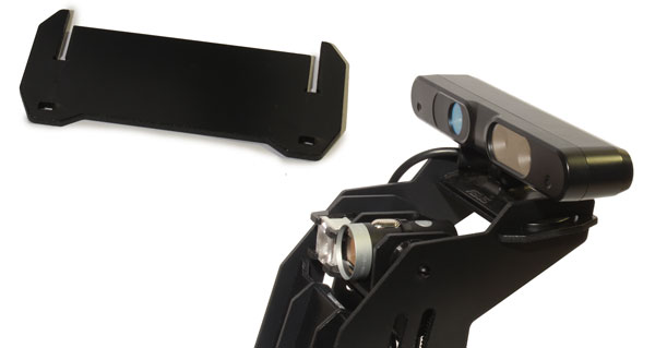
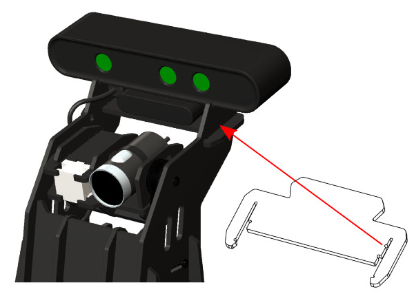
Step 5(B) – Mount Orbbec Sensor
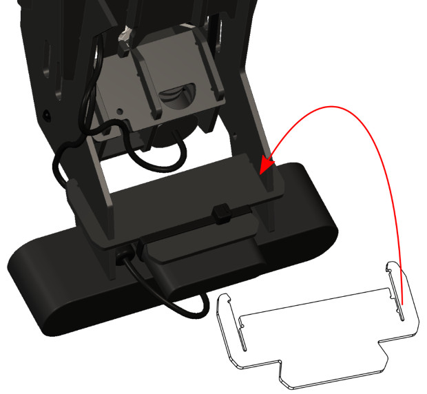
(If applicable) The cable should be routed forward (to keep it from blocking the rear view of the camera). To allow the ferrite chunk on the USB cable to pass thru the frame beside the sensor base, the mounting is offset slightly to one side, and there is a small ‘orientation indicator notch’ in the sensor base support frame part on the opposite side — correct orientation of the part is shown by the red arrow in each view below, pointing to where the indicator notch should be when the part is assembled.
Butt the front of the camera up firmly against the small frame tabs as shown above, then use a single large zap strap secured tightly, to hold the camera to the plate.
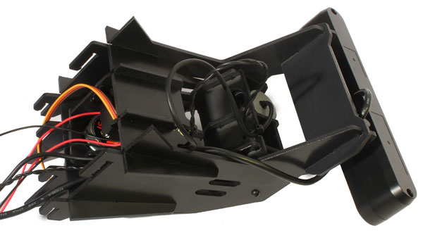
Step 6 – Route Cables
Run the camera, spotlight, and Xtion cables into the cable routing notch in the rear of the upper frame section on robot’s right, as shown below. Leave a generous amount of slack for the camera and spotlight wires, as they need to be free to pivot (you’ll probably have to adjust this later). Note the preferred routing of the xtion cable.
Step 7 – Prepare Top Plate
ANTENNA DRILLING: if you’re mounting wifi antennas, use a 1/4" (6.3mm) bit to drill the antenna mounting holes, using the 2 small non-thru pilot holes as a location guide.
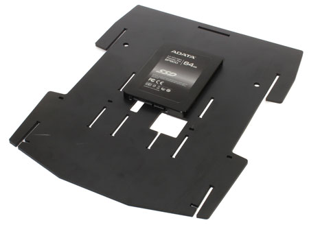
If you have a 2.5" format SSD, now is the time to attach it to the underside of the top plate, using two M3 screws, into the mounting holes nearest the power and data ports:
Step 8 – Attach to Top Plate
With that out of the way, run cables through the rectangular hole in main top plate:
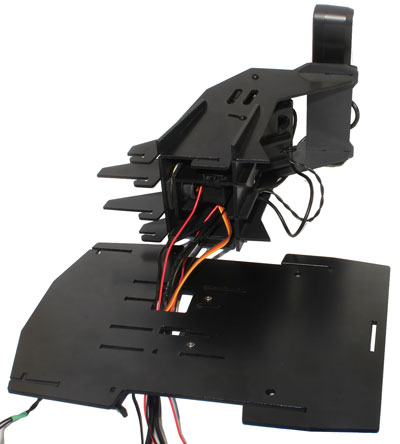
Then, mate the six tabs with their slots in the top plate:
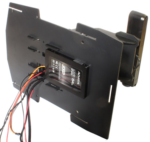
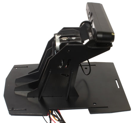
Slide it forward until it clicks, to complete the upper assembly:
NEXT: Chassis Assembly